How to get edge 'island' selection
-
Hello there,
I do not have code for this, I was mostly curious if an idea was at all possible and how to approach it in Cinema's SDK.
Steps to reproduce:
- Create Plane.
- Make it editable
- Switch to Edge mode
- Use Path Selection tool set to Simple Edge loop to select a few loops like this:
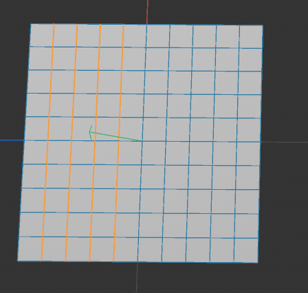
Is there a way to get each of these loops in python? Like, a Base Select would just give me whether or not an edge is selected, but I basically want to get the continuous edges of each loop. So to know that the first loop is made up of edges 1-10, the second loop is 2-20, etc. The end goal would be to take those loops, and do some stuff with each set of verts for each loop. But I am not sure if this is even possible or not. I had looked at the Neighbor class, but I don't know if that would enable me to do it.
There must be some sort of internal method because if you do some loops and use the edge to joint command, it can differentiate the different loop selections to create joints.
-
Hey @BretBays,
Thank you for reaching out to us. Yes, that is possible but we cannot write the script for you. We can only help you when you make the first steps yourself. You will find all the necessary building blocks in the modeling example scripts.
- Create a plane generator object.
- Get its cache to get an editable polygon object. For more complex geometry or in general you could also run
MCOMMAND_CURRENTSTATETOOBJECT. - The run
SendModellingCommandwithID_MODELING_LOOP_TOOL. Sometimes modelling commands can be a bit bumpy ride, when you want to do more niche things. But at the first glance everything you will need seems to be there:
Cheers,
Ferdinand -
Hey Ferdinand,
I didn't give a good enough example, my apologies. And no worries, I certainly don't expect the script to be done for me, it's just hard to know if something is possible or not and if I knew the answer, I'd likely have the script myself :). Let me try to explain it better.
Check out this video: https://www.dropbox.com/scl/fi/ce9d71lg0tnv3j9qz1s9v/WeightBlend.mp4?rlkey=4s3qj0s2trhniwezgo7yf4cy3&e=1&dl=0 it shows the workflow for a plugin I am developing that this request was even for. If you watch, I am working with 2 points along an edge loop before click apply. What would be preferred is to instead define all the edge loops to then click apply and it will do the blending along each loop.
So the question is if there are any means or ways to determine unique edge loops from an edge selection that I could then go through each edge loop, convert to verts under the hood and then do what I normally do for the weight blending.
-
Hey @BretBays,
Thank you for your clarification. I think I understand a bit better what you want, but there are still some question marks for me.
The edge loop and ring loop tool work via point indices (and a bunch of other settings). I.e., you set
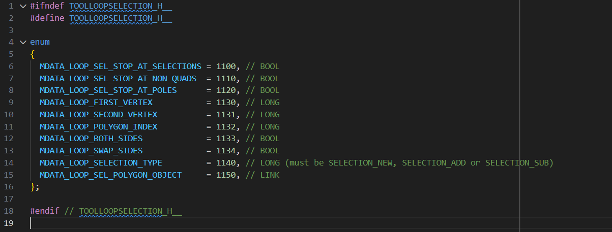
MDATA_LOOP_FIRST_VERTEXandMDATA_LOOP_SECOND_VERTEXand that determines the edge you want to loop (the screenshot above is fortoolloopselection.h, the file which defines the loop tool IDs). As I said above, some of the modelling command options can be bit finnicky, but I would help you crossing that bridge when we are there. But we would have to have a foundation we can work on to get started.Sorting Selections
But from what I understand, you do not primarily want to select loops, but rather sort existing selections into loops, or more generalized: edge strips you consider to be semantically/topologically connected. For something like shown in your screenshot, this is trivial, but a general solution is not. That you have an existing selection is almost irrelevant, it is only slightly easier to solve than the general problem of sorting all edges of a mesh into strips.
I wrote something like this myself a long time ago (while still at university at not a member of Maxon) and struggled quite a bit then to get it right, because you have then to deal with intersecting strips, self intersections of strips, etc. The problem of yours lies generally in the field of topological sorting, which is pretty wide, the concrete term used for the particular problem is often 'edge extraction in mesh processing'. The popular Python mesh processing library
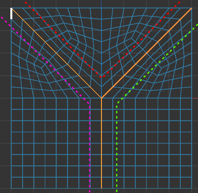
PyVistaimplements for example edge extraction.If your concrete problem is solvable, depends entirely on how well you define it. For just an given input set of edges, there exist often many solutions. You have to define things like a maximum angle of change between edges in a strip, how to deal with intersections of strips, if you want continuity of non-manifold edges, etc. And even then, you will often end up with multiple solutions. E.g., in the example below, there are three possible ways to sort these edges into two strips (and even more when you do set this conditions to minimize the number of strips). Which can be deemed undesirable.
Implementing an Edge Selection Tool Yourself
I do not understand all details of your tool, but when edge selections are part of it, you could also 'simply' integrate them. Your tool looks currently more like a dialog/command and you could also do it there, but an actual
ToolDatawould be better.The general drill would be to add a button/mode with which the user can select edges. Once running, you would use
c4d.utils.ViewportSelectto get the points/edges the user is clicking or hovering. Once the user wants to commit to a selection, you get the two relevant hoovered points (i.e., edge) and runID_MODELING_LOOP_TOOLwith it. Because you would inspect the user creating the loops one by one yourself, you would naturally know what is a strip in the final selection.Here are also some hoops to jump through and there might also be obstacles you cannot overcome which I do not see at first glance either (as actual
ToolDatatools are not very often implemented in Python and therefore a bit niche), but generally this should be possible and this might be less costly than writing a full blown edge extraction solver.Sorting Edge Selections Without Intersections
If you want to sort edge selections without intersections (or touching), this is relatively easy to implement, you only have to get the selected edges, convert them into point pairs, and then sort them into strips by finding point pairs where one point matches the end of another pair. The problem of this route is that it is pretty much guaranteed not to suffice in real world scenarios.
Cheers,
Ferdinand -
Hey Ferdinand, thanks for the detailed response.
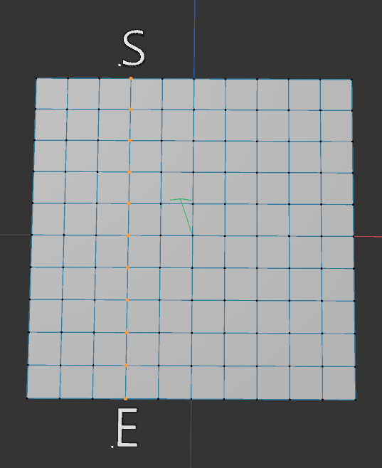
Allow me to expand even further and try to explain some of the issues I have run into. My plugin/tool basically works at the moment via a start point and an end point that sit on the same loop. LIke this image:
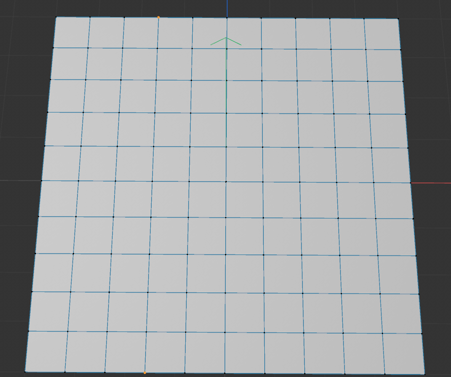
What the plugin does is it looks at the joint weights for one point(designated as the start point) and the weights for the other point(designated as the end point). Then, it gets all the other in between points on the loop path and in order.
Then the plugin does an interpolation of the joint weights from the start to end, and interpolates all those in between point's joint weights. That all works fine and I have a function to get those points based off that joint selection, so no issues there.
From a workflow standpoint, this is fine, but it's slow because I have to go loop by loop manually selecting my start and end points, and go loop by loop. So my idea(based off a maya tool used at work) is to be able to select those loops myself with edges, and have it run the interpolation on all the loops at once(well, at once as far as clicking apply once and it does each loop for you).
The issues I am running into is that it seems like working with edge selections is very cumbersome in Cinema. There is op.GetEdgeS() which will return me a BaseSelect, but I cannot properly query whether or not an edge is selected. Edges dont seem to have their own unique id to where I could do something and say like, "Go select Edge 23 and do something with it". The edge seems to be derived from a polygon's info to be either 0-3 for a given polygon.
I don't know I just am having a hard time wrapping my head around these concepts in Cinema. Is it possible to pass in an edge ID and work with edge ID's or do you have to go through the polygon info and all of that to get them? Like if I could store a list of selected edge ID's(in theory op.GetEdgeS() should do this for me, right?) I could in theory just start with one, then walk through the mesh via growing the selection and appending only edges found in the original selection, then deselecting all the rest. This should in theory allow me to grow along the path and organize them by loop and then I could do things like you said convert them to loops later
-
Hey @BretBays,
Let me answer a few things, I although I still have the feeling we are not at the bottom of things yet.
So my idea(based off a maya tool used at work) is to be able to select those loops myself with edges, and have it run the interpolation on all the loops at once(well, at once as far as clicking apply once and it does each loop for you).
You can of course implement a point, edge, or polygon loop or ring selection yourself. But my advice would be to use the builtin tool programmatically unless you really have to implement your own tool. Because while a simple loop selection is relatively trivial, a production level loop tool is then quite a bit of work, due to all the edge cases you have to handle.
The issues I am running into is that it seems like working with edge selections is very cumbersome in Cinema. [...] I don't know I just am having a hard time wrapping my head around these concepts in Cinema. Is it possible to pass in an edge ID and work with edge ID's or do you have to go through the polygon info and all of that to get them?
Cinema 4D does not store edges explicitly, as this would unnecessarily increase the size of a scene. One can sufficiently describe polygonal geometry as a set of points for the vertices, and a set of ordered quadruples of point indices for each polygon. This is common practice in 3D applications and called 'indexed face set'. You always have to go through the polygons and points to work with edges. Edges are effectively just a smoke and mirrors convenience feature for end users. One could argue how much front-end wrappers for edges an API requires to be easy to use, but I would say Cinema 4D is there at least okay. You can find helper functions for edges on
PolygonObjectandSendModelingCommandsupports edge selections directly.In short, for each perceived user edge E_p, exist n 'real' or 'raw' edges for the indexed face set, where n is either 1 or 2 when the is mesh manifold (or larger when non-manifold). If n=1, then E_p is a boundary edge, otherwise it is an internal edge shared by two polygons. This is due to these two polygons having two have opposite winding orders for that shared edge when the polygons are meant to face into the same direction. The following diagram illustrates this (arrows indicate the winding order of the polygons):
a- → -b b- → -e
|     | |     |
↑  P  ↓ ↑  Q  ↓
|     | |     |
d- ← -c c- ← -f
Fig. 1: Two polygons P and Q sharing the user perceived edge E_p defined by the points b and c. The lower case labels denote unique point identifiers in the indexed face set, not a point order within the polygon. The polygon P is defined as
(a, b, c, d)and the polygon Q as(b, e, f, c), i.e., a and b are the first vertex of each polygon respectively. The arrows describe the winding order of the polygons.The global raw edge index is defined as
rawEdgeIndex = polygonIndex * 4 + localEdgeIndex. E.g., when P would have the polygon index2and Q the polygon index6, then the user perceived edge E_p would correspond to the two raw edges indicesp_bc = 2 * 4 + 1 = 8(edge bc in P which is the second edge, i.e. local index1) andq_cb = 6 * 4 + 3 = 27(edge cb in Q which is the fourth edge, i.e. local index3).Here are some code examples and forum posts about working with edges in Cinema 4D's Python API:
- geometry_polgyon_edges_2024: This is the official example script showing how to work with polygon edges in Cinema 4D 2024. It explains how to access and identify edges in a polygon object.
- Select Edges by Length: An example that shows how to select edges based on their length.
- Select Polygons Facing into the Same Direction: Not directly related to edges, but I talk here about the fundamental concept of a winding order, which is important when working with polygon edges.
Cheers,
Ferdinand