Programing a Tabulated BRDF Node / Shader - possible ?
-
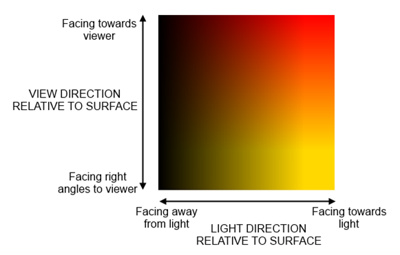
I have a material Properties from a real world material Scan, which represents two different values represented in two gradients X and Y which result in a lookup table I assume. The gradient of the sample is a color shift of "albedo" depending on viewing / light direction.

Is it possible to program a node / Shader for C4D and or Redshift to behave like this. Or is the light direction camera position an Chicken / eg problem that can not be solved outside the core of C4D ?
The question is general because I lack Shader Programing knowledge.
If this thread should be in General feel free to move it.Thank you in advance.
mogh -
Hey @mogh,
Thank you for reaching out to us. That is a very broad question. Shaders for Redshift can only be implemented via OSL. Standard renderer shaders can be implemented via Python but it is a bit debatable how sensible that is.
For the standard renderer, the
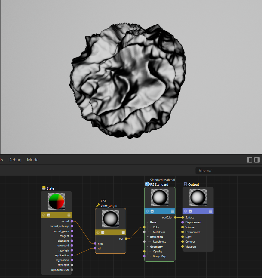
BaseVolumeData.raywill give you the current ray (accessible viaChannelData.vdpassed ascdinto aShaderData.Outputcall). py-fresnel_r13 demonstrates how to implement a view angle dependent shader. For Redshift OSL, things are somewhat similar. There you need theStatenode to get information such as sample normal and ray direction. A very simple setup to do some view angle dependent calculations could look like this:
File: osl_shader.c4dshader view_angle( point rd = point(1.0, 0.0, 0.0), // Ray direction in point nrm = point(0.0, 1.0, 0.0), // Surface normal in float gamma = 5.0, // Gamma value for contrast enhancement output color out = color(0.0, 0.0, 0.0) // Color out ) { // Compute the dot product of the two normalized vectors float dp = abs(dot(normalize(rd), normalize(nrm))); // Apply gamma correction to enhance contrast float gdp = pow(dp, gamma); // Convert the enhanced dot product to a grayscale color out = color(gdp , gdp , gdp); }When you then have some input texture you want to sample based on the angle of incident, i.e., the dot product of the surface normal and inverse ray direction, that would be the very general way to go, only that you then use the dot product as a key in your lookup table(s). As far as I understand you, you just want to implemented some from of iridescent material based on tabulated data?
A good starting point might here also be the Redshift OSL shader repository and the Redshift Forums.
Cheers,
Ferdinand -
Thank you Ferdinand for your guidance.
Redshift sent me here, Adrian said its not possible with OSL because of closure ... https://redshift.maxon.net/topic/51827/how-to-create-a-tabulated-brdf-color-osl-shader?_=1730097777842
But it seems you made something. I am not sure how to "lookup" the color value in my texture but it seems possible.
OSL MatCap Shader does this in a Spherical manner anyway ...
Thanks.
-
Hey @mogh,
Hey, it could very well be that Redshifts Closure paradigm at least complicates things with OSL. But for what I did there, a simple view angle dependent shader, I would say all the data is accessible here.
When I look more closely at your texture, it seems to model true Iridescence, as it maps out both the viewing and illumination angle. Which you cannot do with Redshift shaders atm as there is no such input as a 'light direction', but the Redshift team can tell you probably more. My example only models a simple view angle dependent shader. You would read such texture via the dot product I would say. The angle of incident is the absolute of the dot product of the surface normal and the inverse ray direction (inverse because the ray 'comes in' while the normal 'goes away'). The dot product expresses the angle between two vectors in the interval [0°, 180°] as [-1, 1]. So, when you take the absolute of that, you get [0°, 90°] as [0, 1] which you then can directly use as an UV coordinate. In your example you seem to have to take the inverse as they flip things according to your image (i.e.,
v: float = 1.0 - abs(-ray * normal)). For the light ray it would be the same, it would just replace therayin the former example, and then makeup youru/xaxis.This might be why Adrian said that this is not possible. It is better to ask there the Redshift team, as my Redshift knowledge is somewhat limited. For the Standard Renderer, you would have access to all that data, but that would result in a shader you can only use in Classic materials of the Standard Renderer. But you would have to use the C++ API, as you would have to start digging in the VolumeData to get access to the
RayLightdata.Maybe you could fake the light angle in some manner to get a semi-correct result?
As a warning though, what Adrian wrote there about the C++ SDK strikes me as wrong. There is a semi-public Redshift C++ SDK, but I doubt that it will allow you to write shaders for Redshift, due to how the Nodes API is setup. You can implement shaders for your own render engine, but neither Standard nor Redshift render shaders are really implementable for third parties right now.
Cheers,
Ferdinand -
Thank You Ferdinand,
This Problem is not mission critical here, but it kept coming at me (at night). Anyway this is hopefully useful for others in some way, as its to complex for very little gain in my case ... I can fake a similar material with Fresnel colors and some falloff / or even thin film hacks.
If anybody wonders, the Scan (gradient) is from an X-Rite Material Scanner (TAC) which normally has a proprietary file format.
Thank you for your time regardless.
mogh -
Hey,
Out of curiosity, I did some poking in Redshift, and what I forgot, is that you are in principle unable to escape the current shading context of a sample in Redshift. I.e., you cannot just say, "screw the current UV coordinate, please sample my texture 'there'" due to the closure thing which Redshift has going.
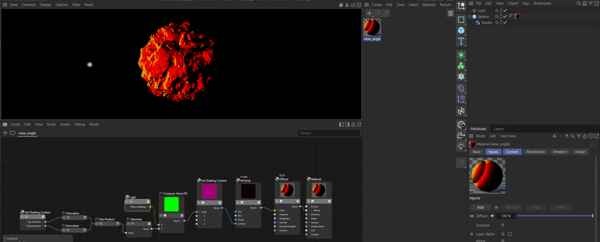
With the Standard Renderer, you can do the following, which is pretty close. I compute the v (i.e., view angle coordinate) as described above. Standard also does not give you directly light ray angles, but you can get the light contribution where I use the diffuse component of the light(s) as a faksimile: High diffuse = high angle of incident/light contribution.

Fig. I: A crude iridescence setup in Standard.test.pngis your texture from above, I forgot to take the inverse of values as1 - x.In Redshift you cannot do the same light contribution hack, and I currently do not see how you could set the sampling coordinate of the texture in the first place. Maybe the Redshift pro's know more.
Cheers,
Ferdinand