I found the solution (I already had this problem but I couldn't remember the right code)
mat [c4d.MATERIAL_TRANSPARENCY_COLOR] = c4d.Vector (1.0, 1.0, 1.0) #color white
mat.Update (True, True)
I found the solution (I already had this problem but I couldn't remember the right code)
mat [c4d.MATERIAL_TRANSPARENCY_COLOR] = c4d.Vector (1.0, 1.0, 1.0) #color white
mat.Update (True, True)
I found the solution to my problem, on the internet, with code samples:
https://www.c4dcafe.com/ipb/forums/topic/101805-materials-and-shaders-with-python/
I have a string variable whose value is the identifier of a spline:
<c4d.SplineObject object called 'Spline1/Spline' with ID 5101 at 0x000001D672DC4F70>
Given this identifier, how do I get a spline-type variable ?
@ferdinand
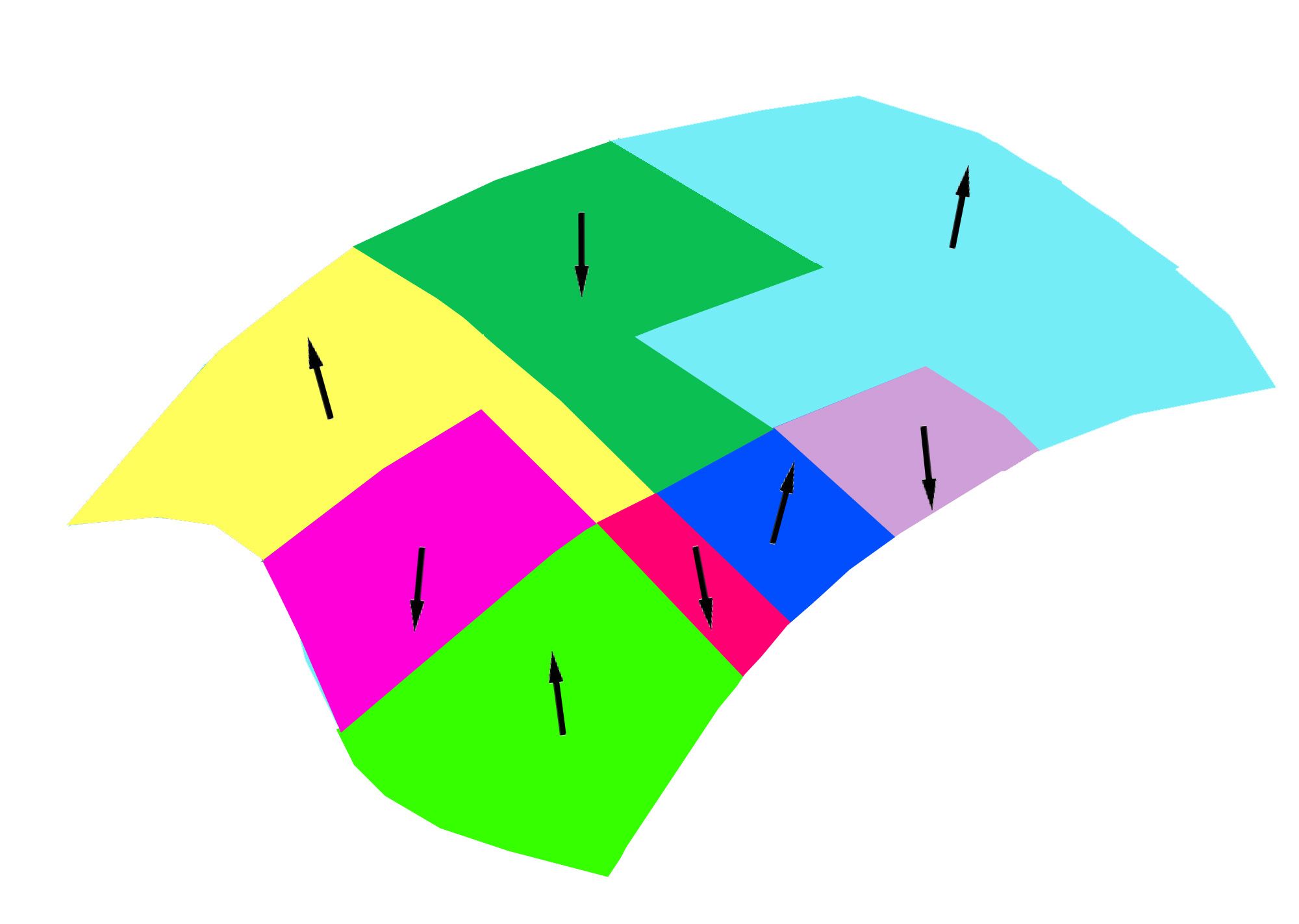
I'm showing an example with a curved surface composed of 8 zones.
Each zone is the union of several polygons with normals oriented in the same direction (represented by an arrow).
I think C4D should be able to identify this type of tiling and colorize these areas to highlight them.
Depending on the case, this tiling could be important, but most often, creators assemble the faces logically.
A window could then offer the option to select each tiling, in order to invert the normals with a single click.
A plugin could also do this kind of work, which would save creators time.
@seora
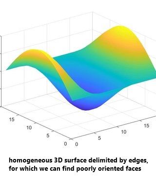
If you take a simple, seamless 3D surface bounded by edges, you can almost always create two distinct sets of faces with the same orientation. Thus, under certain conditions, you can find the misoriented faces with a Python program.
But generally, since C4D coding cannot find how a polygon should be interpreted, finding misoriented faces is geometrically impossible. Only an AI program could list possible scenarios to answer this question (knowing that several scenarios exist).
On the other hand, if your Python program knows the target shape you're working on (cube, sphere, ellipse, torus, etc.), you can find the misoriented faces very easily.
From a purely mathematical point of view, there must exist a set of polygons for which this extraction is theoretically possible, given how C4D encodes faces.
But I think there must exist many polygons for which this possibility makes no sense. For example, a Möbius strip where there is no back and no front for a face.
Hi
The menu Mesh > Convert > Connect Objects allows you to connect polygons.
I need to make this type of connection with a Python script.
My current script isn't working properly.
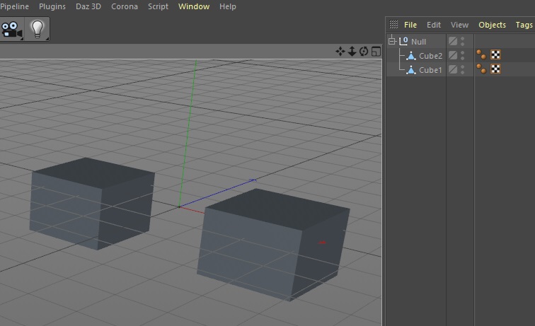
The following example illustrates my problem.
In this example, I translate and rotate the ring using C4D's interface.
In figure 1, the ring is at point (0,0,0) with an angle of zero.
Figure 1
In figure 2, using the Cinema 4D interface, I translate the ring with the vector <2,1,3> in centimeters.
Then I performed three successive rotations: 322° on the X axis, 30° on the Y axis and 343° on the Z axis.
Cinema 4D positioned the axis center of the ring correctly.
Figure 1
But when I create my ring with 4 splines, at a point in space other than (0,0,0), the axis center always remains at the point (0,0,0) with an angle of zero.
I'd like the axis center to be at the center of my ring and at the same angle as in Cinema 4D.
Let me explain.
My problem may be complicated to understand, but my final request is very simple.
In C4D, I've got into the habit of creating my 3D objects with splines, which allows me to create objects of any kind.
I do this with Python.
So to create a ring, I create 4 splines. Then, with these 4 splines, I create the ring.
If my 4 splines are centered on the point (0,0,0) as shown in the image below, my ring lies on the XZ plane.
The axis center of the ring is also on the point (0,0,0). What's more, it's well oriented, as its Y axis corresponds to the Y axis of my ring.
Furthermore, the X axis of the axis center is aligned with the segments connecting the point (0,0,0) with the first points of my construction splines.
In this case, everything is perfect.
Figure 1
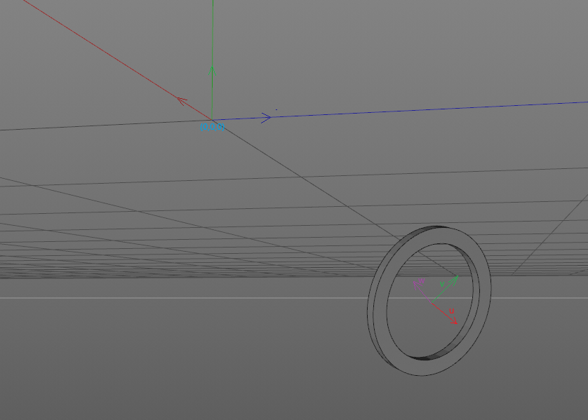
However, if the center of my 4 splines is elsewhere and the orientation is arbitrary, as shown in the image below, this is where the problem arises.
After creating my ring, the axis center remains at the point (0,0,0) and its orientation is identical to the previous case.
Figure 2
So I need to use Python to bring the axis center back to the center of my ring (translation).
Next, I need to rotate the axis center so that its Y axis is perpendicular to the plane of my ring.
Next, I need to rotate the axis center around its Y axis, so that its X axis is parallel to the segments connecting the center of the ring with the first points of my construction splines.
In conclusion:
I need the following functions:
Hi,
With python, I generate a ring in space that is far from the center (0,0,0)
The ring is in the plane formed by two vectors u and v.
The vector w is perpendicular to the ring.
After creating the ring, its center axis is at the position (0,0,0)
I would like to place the center axis at the center of the ring whose position I know.
In addition, I would like the axes of the center axis to correspond to the base (u,v,w) in which I created the ring.
I made this function which works fine:
def spline_update(doc,spline,tabNewPoint):
	tabPoint = spline.GetAllPoints()

	dim = len(tabNewPoint)
	if len(tabPoint) != dim:
		spline.ResizeObject(dim)

	for i in range(0,dim):
		point = tabNewPoint[i]
		spline.SetPoint(i,point)

	spline.Message(c4d.MSG_UPDATE)
	return spline
Hi
How to update a spline if the number of points changes ?
If the number of points is the same, we can use the following function:
def spline_update(spline,tabPoint):
	dim = len(tabPoint)
	for i in range(0,dim):
		spline.SetPoint(i,tabPoint[i])

	spline.Message(c4d.MSG_UPDATE)
	return spline
If the number of points changes, we must use the ResizeObject() method
I'm looking for an example, which will save me from doing tests.