
Describes different patterns of implementing nodes and their core functionality of computing outputs with a list of inputs.
From a mathematical point of view, a true node in a node graph is an operation. That operation takes a list of inputs and returns a list of outputs. That functionality could be for example adding two values and returning the sum of them. Because of that, the most basic implementation of a node functionality is providing a delegate which implements the functionality of a node. The example below implements the operation of taking an input value and returning its absolute value as the return value of a delegate.
This delegate can also be realized in the form of a type agnostic template. Which can be useful when there are many input data types which the functionality can be applied to.
For unary operations, the MAXON_CORENODE_OPERATOR_UNARY macro can be used to streamline the process of registration. A unary operation is an operation with a single operand and a single output. Taking the absolute or the inverse of a value is an example of unary operation.
For binary operations, the MAXON_CORENODE_OPERATOR_BINARY macro can be used to streamline the process of registration. A binary operation is an operation with two operands and a single output. Summing up or comparing two values are examples for binary operations.
The MAXON_CORENODE_FUNCTION, MAXON_CORENODE_OPERATOR_UNARY and MAXON_CORENODE_OPERATOR_BINARY macros simplify a core node implementation if the function is already available as a C++ function or operator. Such node implementations then need to be registered with MAXON_CORENODE_REGISTER_PURE macro.
CoreNode implementations that can handle multiple data types for a singular input value have to be registered for each data type this input value can be.
Every time a CoreNode is being implemented, a custom user node has to be created and linked to the CoreNode. For details read Implementing Custom User Nodes. Depending on the operator node type which is being implemented, the custom user node will need one or more input ports.
More specifically:
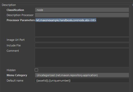
To establish the connection of a custom user node's port identifiers and the CoreNode in- and outputs, a processor directive has to be provided in the Resource Editor. In the database for your plugin, click on an empty part of the tree view to have no element of the currently displayed data type selected and define the value of the processor parameter in the view on the right as:
CoreNode implementations can also be provided in the form of class implementations, providing more options than the callback approach.
BasicMicroNode is the base class for implementing the functionalities of a core node. It is comparable to NodeData in the classic API as it is also a central interface with which plugins will be implemented. While NodeData implemented arbitrary (GeListNode) nodes in the scene graph of the classic API, BasicMicroNode does the same for the Nodes API and implements a CoreNode. A BasicMicroNode receives a single set of input values in its Process() method and computes for it the output values defined by its functionality. A minimal BasicMicroNode implementation has to provide port definitions and its Process() method. The ports have to be defined by MAXON_PORT_INPUT or MAXON_PORT_OUTPUT macros in a group class. Usually, the BasicMicroNode class is a member of that micro node group class, as shown in the example below.
BatchMicroNode is the base class for custom micro nodes which receive a batch of input values in their Process method and compute the corresponding output values. If Process() method of a BasicMicroNode implementation only consists of a few simple operations, one will consider implementing a BatchMicroNode instead. It computes the output values for a whole batch of input values with a single call, reducing the calling overhead of nodes. The calling overhead of nodes can be significant, and it can be reduced when a single call to Process() handles a whole batch of values. But this only holds true, when there is a batch of values. In the context of shading for example, there is usually just one set of values. A Process() method implementation for a BatchMicroNode has then to loop over a batch of data as shown in the example below.
The OperatorNode is a helper class to implement core nodes. This core node will be composed of a function, where some data processing will be defined, and a single output port. This processing function has parameters, one reference to the output port, and references for each entry port to retrieve their values. If this class has template arguments, the operator node must be registered with all the data types that this node can handle.
This example shows how to create such an OperatorNode. The CoreNode with the id net.maxonexample.handbook.corenode.operator.sin this will be used later as a parameter for the Description Processor.
Now that the CoreNode is implemented, the user node can be created with the Resource Editor. For more information please have a look at Implementing Custom User Nodes
net.maxonexample.handbook.nodes.trigonometry.sin.datatype. Set its data type to id, its classification to Input, and define the Gui Type ID to net.maxon.ui.enum. This cycle will be filled automatically with the data types that have registered for the CoreNode.in and the output port identifier will be out. Check "Is Converter Node" so the input and output will be automatically connected to the wire if a user drops the node on a wire that is compatible with the data type.datatype with the check-boxes Data, UI and String checked. Define the datatype as id and the string to Data Type.CoreNode Description Processor. This field allows defining which description processor will instantiate and register the template for this data type. The field Additional Parameter is where is defined what core node will execute its code to process the data. For this, enter the identifier of the CodeNode created previously.net.maxonexample.handbook.corenode.operator.sin<datatype>. This also makes the Description Processor aware that it have to fill the enum list of the data type port with the enum list of the registered data types registered for this CoreNode.Short circuit rules are a set of conditions defined when creating a CoreNode that will allow the CoreNode to know the result of its process function without processing the data. For example, a node that multiplies a port A with port B, if one of the values is zero, no matter what the value of the other port is, the result will be zero. If one of the values is 1, the result will be the other value unmodified. In those cases, the result does not need to be calculated.
The ShortCircuitRule must be created and registered with the same macro that is used to register the CofreNode itself. As this CofreNode is usually a simple node, OperatorNode or OperatorBinary can be used. The CoreNode must be registered with metadata to define the optimizer it must use.
The following example shows how to use a binary operator to create a boolean node that processes an AND operation with short circuit rules to process the operation faster.
This is the same with an OperatorNode. In this example, the class and the function that will process the data must be defined.
A BasicMicroNode implementation can also be used to provide a selectable constant. This will be then, from an end-user point of view, a node without an input, as the user will usually only select the constant manually in a drop down menu. But the selected value of the drop is still an input port which could be driven. Examples for constants which could be provided in such a way would be mathematical constants like the numbers PI and e, a null-vector or physical constants like a certain color temperature in Kelvin. This can be implemented with a BasicMicroNode and a switch statement at the heart of its Process() method. The value of the input port, the drop down menu, could be interpreted as an enum for more clarity in a code project.
But the node description system also allows for declaring the port data type directly as shown in the screen-shot below. If the port should not to appear in the node editor, in order to present it as a node "without inputs" to the user, the option "Hide Port in Nodegraph" has to be checked for the input port.
