Graph Description Manual
Learn how write scripts that generate and update node materials using the graph description syntax.
Overview
Graph descriptions are a simplified approach to creating and updating node materials. Common use cases for graph descriptions are:
Creating new materials based on sets of textures and material metadata, as usually provided by material websites.
Updating parts of existing materials, as for example change the color profile in all textures in all materials in a scene.
Graph descriptions hide away some of the verboseness of the Nodes API when using identifiers and wiring up graphs by introducing lazy syntaxes and implicit wirings. A graph description will require roughly two-thirds less lines of code than a comparable Nodes API script. But graph descriptions are not meant to be a replacement for the Nodes API but a human readable data format for graphs. For complex tasks and full access to nodes data you will still need the Nodes API.
import math
import maxon
from maxon import GraphDescription

GraphDescription.ApplyDescription(
    GraphDescription.CreateGraph(name="Basic Example"), {
        GraphDescription.Type: "Output",
        "Surface": {
            GraphDescription.Type: "Standard Material",
            "Base/Color": maxon.Vector(1, 0, 0),
            "Base/Metalness": 1.0,
            "Reflection/IOR": 2 * math.pi
        }
    }
)
Fig. I: A simple graph description and its output, a red metallic material in the Redshift node space.
A graph description describes a graph as a set of nested Python dictionaries where nodes are listed in a right-to-left order. Usually we read a node graph left-to-right, we read from the input nodes to the singular output node of the graph, its so called end-node. A graph description flips this on the head and describes a graph in the opposite direction, starting out with the end node and cascading from there into its inputs. When we take the example from Fig.1, we would normally read this as Standard Material, Output. The graph description flips this on the head and describes the graph in the order Output, Standard Material.
A graph description is composed of a nested set of scopes where each scope describes a node in the graph. A scope is a Python dictionary that contains the node’s type, its input ports, attributes, and other settings. Ports can either be set to a literal value (5 or maxon.Vector(1, 0, 0)) or from a connection to another node by describing a new node as their value. This in combination with the ability of graph descriptions to reference node types and ports over their interface labels aims for a compact and human readable syntax. Find below a commented version of the simple graph description shown in Fig. I.
import math
import maxon
from maxon import GraphDescription

# A GraphDescription.ApplyDescription call must take at least two arguments:
GraphDescription.ApplyDescription(

    # 1. A graph to write the description to, in this case we use CreateGraph to create a new node
    # material and get its graph for the currently active material node space; Redshift by default.

    GraphDescription.CreateGraph(name="Basic Example"),

    # 2. And the graph description to write into that graph. It follows the inverted, right-to-left
    # pattern mentioned before. Each node in the graph has its own scope (a pair of curly braces)
    # in the graph description.

    {
        # This outmost scope is of type "Output". It tells Cinema 4D that we want to create an
        # output node. Instead of GraphDescription.Type, we could also write "$type".

        GraphDescription.Type: "Output",

        # We reference its 'Surface' input port to either set a value or connect it to another
        # node. In this case we crate a new node, indicated by opening a new scope (the set of
        # curly braces). Because most (material) nodes only have one output port, we do not have
        # to specify here that we want to connect to the 'outColor' port of the 'Standard Material'
        # node we are going to create, the output port is implicit.

        "Surface": {
            # Just as before, we declare the type of node this scope describes.
            GraphDescription.Type: "Standard Material",

            "Base/Color": maxon.Vector(1, 0, 0),
            "Base/Metalness": 1.0,
            "Reflection/IOR": 2 * math.pi
        }
    }
)
Technical Overview
The graph description API is part of the Nodes Framework. The relevant entities are:
maxon.GraphDescription.ApplyDescription(): Applies a given graph description to a given nodes graph.maxon.GraphDescription.CreateGraph(): Creates or returns a nodes graph for a given scene element and node space.maxon.GraphDescription.PARSE_FLAGS: Expresses options when parsing graph descriptions.maxon.GraphDescription.QUERY_FLAGS: Expresses options when querying a graph for nodes.maxon.NodeSpaceIdentifiers: Holds the identifiers for all node spaces shipped with Cinema 4D.
Special Fields
The graph description syntax uses special fields that neither reference ports nor attributes of a node to convey metadata about node or graph. The most important of these fields are:
maxon.GraphDescription.Type: The type of the node this scope describes. Alias for"$type".maxon.GraphDescription.Id: The identifier of the node this scope describes. Alias for"$id".maxon.GraphDescription.Query: Used to query a graph for nodes. Alias for$query.maxon.GraphDescription.QueryMode: Used to specify the query mode of a query scope. Alias for"$qmode".
Note
This manual will use the string aliases for these special fields in the following examples.
Limitations
Graph descriptions are a new feature in the Cinema 4D Python API and have some limitations at the moment.
English is the only supported language for interface label identifiers at the moment.
Group nodes and scaffolds are not supported.
Variadic ports are currently bugged.
Explicit output ports are currently not supported.
Graph queries currently do not support nested queries.
Graph descriptions do not support scene nodes at the moment.
Basic Features
Getting Graphs
An important aspect of writing graph descriptions is to get the graph to write the graph description to. The function maxon.GraphDescription.CreateGraph() is a convenance function to hide away some of the technical Nodes API details of that task. It can be used to both create and get a graph for a given scene element and node space. The example shown below demonstrates a few use cases of the method.
import c4d
import maxon

from maxon import GraphDescription
from mxutils import CheckType

doc: c4d.documents.BaseDocument  # The currently active document.

# The most common use case for CreateGraph is to create a new material and graph from scratch.
# This will result in a new material being created in the active document with the name "matA".
# Since we  are not passing an explicit node space, the currently active material node space
# will be used.
graphA: maxon.NodesGraphModelRef = GraphDescription.CreateGraph(name="matA")

# This will create a material named "matB" that has a graph in the Redshift material node space,
# no  matter what the active  material node space is.
graphB: maxon.NodesGraphModelRef = GraphDescription.CreateGraph(
    name="matB", nodeSpaceId=maxon.NodeSpaceIdentifiers.RedshiftMaterial)

# But we can also use the function to create or get a graph from an existing material. The call below
# will either create a new Redshift graph for #material or return the existing one.
material: c4d.BaseMaterial = CheckType(doc.GetFirstMaterial())
graphC: maxon.NodesGraphModelRef = GraphDescription.CreateGraph(
    material, nodeSpaceId=maxon.NodeSpaceIdentifiers.RedshiftMaterial)

# We can also pass a document or an object for the first argument #element of CreateGraph. If we
# pass a document, it will yield the scene nodes graph of that document, and if we pass an object,
# it will yield its capsule graph (if it has one).
sceneGraph: maxon.NodesGraphModelRef = GraphDescription.CreateGraph(doc)
# capsuleGraph: maxon.NodesGraphModelRef = GraphDescription.CreateGraph(doc.GetFirstObject())

# Finally, we can determine the contents of a newly created material graph. We can either get an
# empty graph or the so-called default graph with a few default nodes as it would be created in
# Cinema 4D when the user creates a new graph for that space.
emptyGraph: maxon.NodesGraphModelRef = GraphDescription.CreateGraph(name="emptyMat", createEmpty=True)
defaultGraph: maxon.NodesGraphModelRef = GraphDescription.CreateGraph(name="defaultMat", createEmpty=False)
Identifiers
When describing a graph we must reference its entities such as the type of a node or one of its ports. In graph descriptions this can be done by the interface labels of these entities or their API identifiers as used in the Nodes API.
Interface Labels
Other than the Nodes API, graph descriptions can reference node types, ports, and attributes by their interface labels. The evaluation of these references is lazy, meaning that you only must type out what is required to uniquely identify the entity.
The Standard Material node shown in Fig. II has a port named Color in its Base category. Because there are other ports in this node that are also named Color, as for example the Reflection/Color port, we must at least include the attribute group Base to reference the port as "Base/Color". Note that the tabs seen at top of the Attribute Manager on the left (Basic, Preview, Base Properties, etc) are also attribute groups.
If there were somewhere another port named Color with an attribute group named Base, we would have to be even more specific in our reference and write "Base Properties/Base/Color". On the other hand, we can reference entities such as the Metalness port simply as "Metalness" because the label is unique in the “Standard Material” node. When referencing node types itself such as "Standard Material", there is not such a thing as attribute groups with which the label could be disambiguated.
There is no guarantee that all node types, ports, and attributes can be referenced by their label as some entities might be unresolvable ambiguous. In such case one must reference the entity by its identifier.
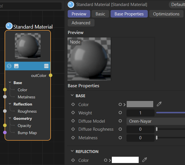
Fig. II: Complex nodes such as the Redshift Standard Material node often have ambiguous port names where we must be more specific in our label references.
Note
Interface label identifiers are supported only in the English (“en-US”) language at the moment. Interface label identifiers can only be used for node type identifiers and port and attributes identifiers, but not port value identifiers. E.g., when you have a node with a port named “Type” whose value is a dropdown with the interface labels “a”, “b”, and “c”, you cannot set the value of the “Type” port by these interface label and instead must use their API identifiers. See Resource Editor for how to discover these identifiers.
import maxon
from maxon import GraphDescription

GraphDescription.ApplyDescription(
    GraphDescription.CreateGraph(name="Basic Example"), {
        # This is a label reference to a node type.
        "$type": "Output",
        "Surface": {
            # This is also a label reference to a node type.
            "$type": "Standard Material",
            # This is a label reference to an input port. We need here the "Base/" because the
            # node has more than one "Color" port.
            "Base/Color": maxon.Vector(1, 0, 0),
            # This would be even more precise but is not required in this case.
            "Base Properties/Base/Color": maxon.Vector(1, 0, 0),
            # This is unambiguous because the "Metalness" port is unique in the node.
            "Metalness": 1.0,
            # This is not unambiguous, it will raise an error as there are many ports called
            # "Color" in this node.
            "Color": maxon.Vector(1, 0, 0)
        }
    }
)
Cinema 4D will tell you when a reference is ambiguous or not found in an error message. The line “Color”: maxon.Vector(1, 0, 0) in the example above will for example raise the following error in the Python console of Cinema 4D.
...
RuntimeError: The node attribute reference 'Color' (space: 'com.redshift3d.redshift4c4d.class.nodespace',
lang: 'en-US', node: 'com.redshift3d.redshift4c4d.nodes.core.standardmaterial') is ambiguous.
Use a more precise reference or one of the IDs:
{net.maxon.node.base.color, ... here it lists all the identifiers which match the given label ...}
In:
    { <- Error in this scope ->
        Metalness: 1
        $type: Standard Material
        Base/Color: (1,0,0)
        Base Properties/Base/Color: (1,0,0)
        Color: (1,0,0)
    } [graphdescription_impl.cpp(167)]
API Identifiers
But node types, ports, and attributes can also be referenced by their API identifier as commonly done in the Nodes API.
To discover such node identifiers, open the Preferences menu from Edit/Preferences in the main menu. There select the Node Editor category and enable the option IDs. When you select now a node in the Node Editor, you will see its identifiers in the selection info box in the lower left corner. The Asset Id of a node is its type identifier, it must be used when a node is instantiated, in graph descriptions with the GraphDescription.Type field. The Id of a node or port is the identifier for that specific instance of something. For nodes it can be used to reference an existing node in a graph or graph description, for ports it is used to reference a port in a node. To see the Id of a port, you must select the port in a node.
API identifiers in graph descriptions are always prefixed with a hash so that can be disambiguated from label references. Identifiers can also be written lazily using the tilde character at the start or end of an identifier. The Redshift Standard Material node has the identifier com.redshift3d.redshift4c4d.nodes.core.standardmaterial and its full reference would be that string prefixed by the # character. But we can also simply write #~.standardmaterial to match an ID that ends with .standardmaterial, we build here on the assumption that this is only the case for exactly on node type. Just as for label references, Cinema 4D will raise an error when a lazy identifier is ambiguous or has no match at all. Lazy port identifiers are matched in the context of the node they are used in and also split by in- and output ports. This means that one for example has only to worry about avoiding collisions between input ports of a node type when lazily referencing an input port of that node type.
Note
Absolute input port identifiers require a “<” character between the hash and the identifier as seen in the node editor. Output port identifiers require a “>” character in the same place instead. This is because these strings are actually not identifiers but node paths from the true node holding these ports.
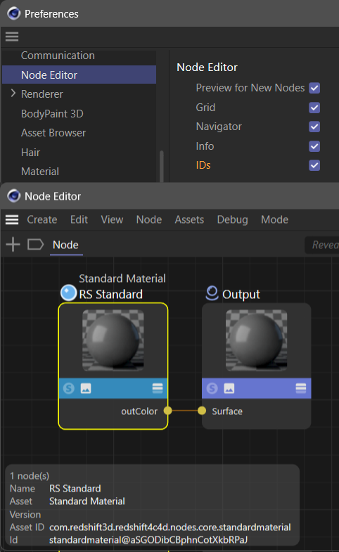
Fig. III: Once enabled in the preferences, the Node Editor can show the IDs and Asset IDs of selected nodes and ports.
The simple example written with absolute API identifiers and once with lazy API identifiers.
import maxon
from maxon import GraphDescription

# The description with absolute identifiers, this gets a bit crowded quite quickly.
GraphDescription.ApplyDescription(
    GraphDescription.CreateGraph(name="Basic Example"), {
        # An output node.
        "$type": "#com.redshift3d.redshift4c4d.node.output",
        # Its surface input port.
        "#<com.redshift3d.redshift4c4d.node.output.surface": {
            # A standard material node.
            "$type": "#com.redshift3d.redshift4c4d.nodes.core.standardmaterial",
            # And its base color, metalness, and reflection IOR input ports.
            "#<com.redshift3d.redshift4c4d.nodes.core.standardmaterial.base_color": maxon.Vector(1, 0, 0),
            "#<com.redshift3d.redshift4c4d.nodes.core.standardmaterial.metalness": 1.0,
            "#<com.redshift3d.redshift4c4d.nodes.core.standardmaterial.refl_ior": 1.5
        }
    }
)
import maxon
from maxon import GraphDescription

# The same description with lazy identifiers, this is much more readable. It is recommended
# to include leading dots in lazy identifiers, i.e., "#~.base_color" and not "#~base_color"
# as we prevent matching against "net.maxon.node.foobase_color" with that.
GraphDescription.ApplyDescription(
    GraphDescription.CreateGraph(name="Basic Example"), {
        "$type": "#~.output",
        "#~.surface": {
            "$type": "#~.standardmaterial",
            "#~.base_color": maxon.Vector(1, 0, 0),
            "#~.metalness": 1.0,
            "#~.refl_ior": 1.5
        }
    }
)
Nested Ports
There are two cases of nested ports in the Node Editor. The Nodes API calls these port bundles and variadic ports. Port bundles are the representation of complex data types where the user can set the whole data type at once - automatically connecting all its children - but also individually its fields one by one. Variadic ports are ports where a user can dynamically add and remove child ports which itself can then be port bundles.
Fig. IV shows a Redshift Texture node at the top which has a Filename port bundle. The port has child ports to describe aspects of the set file such as a path, color space and more. Shown at the bottom is a Standard Renderer Material node. Its Surface port is a variadic port, the difference is indicated by the Add and Remove buttons that can be found in the Attribute Manager and the “+” and “-” shown when a child port of the variadic port is being hovered. A variadic port also has children (which themselves often have children) but the main difference is that the user can remove and add the direct children in a variadic port while the port bundle is static.
Addressing the Filename port bundle itself is not any different than addressing a normal port. We could do it as a label reference with "Filename" or "Image/Filename" or as an API identifier with "#~.tex0". When we want to address a child port of a port bundle, we must append the child port’s label to the parent port’s label with a slash in between, e.g., "Image/Filename/Path" to reference the Path port. For an API identifier it works similarly and the lazy node path for the Path port would be "#~.tex0/path". For a variadic port, this works mostly analogously. We could address the BSDF Layer port in the Material node as "#~bsdflayers/_0/bsdflayer" using a lazy node path. To address that port using labels we would have to write "Surface/BSDF Layer.0/BSDF Layer".
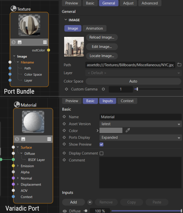
Fig. IV: Shown at the top is a Redshift Texture node with the port bundle Filename. Shown at the bottom is a Standard Renderer Material node with the variadic port Surface.
Warning
Variadic port references are currently bugged, preventing both label and identifier references in some cases. It is also not possible to create variadic ports at the moment. This will be fixed in a future release.
Building Graphs
Scopes and Literals
Each node in a graph description is described by a scope. A scope is a Python dictionary, denoted by curly braces, that contains the node’s type, its input ports, attributes, and other settings. To connect two nodes, a new scope is nested inside the scope of the node to connect to. A side effect of this is that graph descriptions construct a graph from its output to its inputs and not from the inputs to the output as we would usually read a graph.
A scope describes its node as key-value pairs. The non-functional scope {"Base/Color": maxon.Color(1, 0, 0)} for example has the key "Base/Color" which describes an input port by its label and a value that is the color red. Here we have assigned a literal value to the port, which means that we did not construct another node to set the value of the port, but set it directly. But we could also assign a new scope to the port and with that to connect it to another and new node. This is done by opening a new scope inside the scope of the node to connect to. The scope {"Base/Color": {"$type": "Texture"}} for example would connect the Color port of the described node to a new node of type Texture.
When we look at the nested scope in {"Base/Color": {"$type": "Texture"}} we can see an unusual key named "$type". It is an alias for maxon.GraphDescription.Type and is used to declare the mandatory type of the node a scope describes. There are multiple special keys that can appear in a scope and they are all prefixed by a $.
Note
Use Partial Descriptions when you want to construct graphs that do not terminate into a singular node.
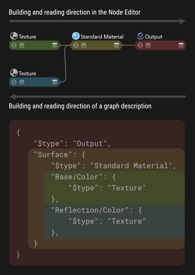
Fig. V: Graph descriptions have an inverted reading direction compared to the Node Editor, the outmost/first node described is the node all other nodes are connected to.
Referenced Nodes
Another special key that can appear in a scope is "$id" which is used to set the identifier of a node in a graph. When we want to connect an existing node in a graph description, we can pass its identifier prefixed by the hash character as the value of the port where we want to connect the node to. The scope {"$type": "Texture", $id": "mytex"} defines a node of type Texture with the identifier "mytex". We can now connect this texture node to the color port of a another node by writing {"Color": "#mytex"}. Node identifiers must be unique in a graph to work correctly and a graph description must define a node and its identifier before it is referenced.
Note
Referenced nodes are the more complex feature of Graph Queries in disguise.
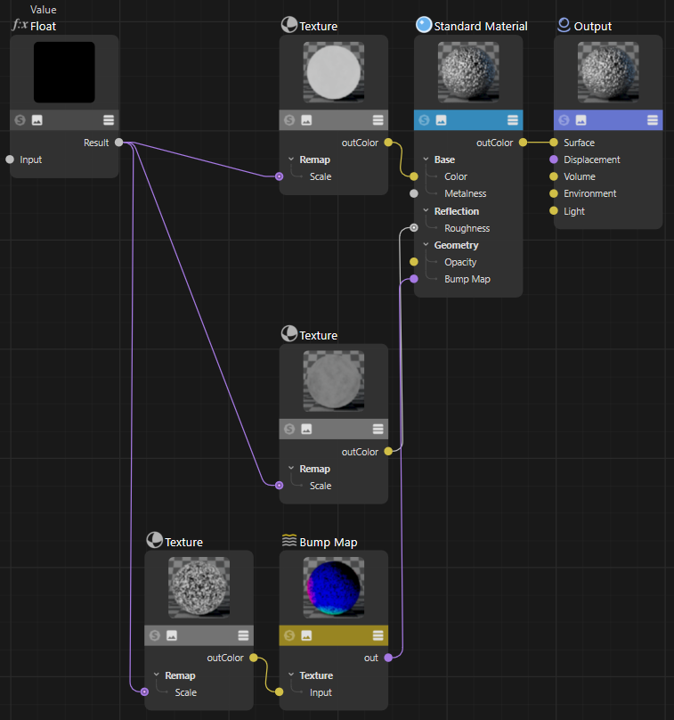
Fig. VI: This graph is created by the Scopes and Values Example shown below, it demonstrates the use of scopes and values in graph descriptions, as well as the use of the $id field to reference nodes in a graph description.
The example shown below creates a more complex setup than the simple examples shown before, demonstrating the inverted structure a graph description uses to describe a graph compared to our reading habits in the Node Editor. Shown is also the use of the $id field to reference a node again in a graph description.
import maxon
from maxon import GraphDescription

GraphDescription.ApplyDescription(
    GraphDescription.CreateGraph(name="Scopes and Values Example"), {
    "$type": "Output",
    # The surface input port of the output node does not have a literal value but describes
    # its value with a nested scope (the {}).
    "Surface": {
        # Directly described is a standard material node.
        "$type": "Standard Material",
        # The metalness port is set as a literal value, here we do not open a new scope.
        "Base/Metalness": 1.,
        # But the base color is not a literal but connected to a texture node, we open a new scope.
        "Base/Color": {
            "$type": "Texture",
            # We set a literal value to the port-bundle child port Path by referencing an asset
            # by its asset URL. If we wanted to reference a file on disk, we would use the "file"
            # scheme, e.g., "file:///C:/path/to/file.png".
            "Image/Filename/Path": maxon.Url("asset:///file_eb62aff065c50a2b"),
            # The scale of the texture is again not a literal but connected to a value node.
            "Scale": {
                "$type": "Value",
                # Here we do something new, we set the id of this node in the graph so that we
                # can later reference it as #texTransform.
                "$id": "texTransform",
                "Input": maxon.Color(2, 2, 1)
            }
        },
        # The reflection roughness of the Standard Material node, we use another texture here.
        "Reflection/Roughness": {
            "$type": "Texture",
            "Image/Filename/Path": maxon.Url("asset:///file_8bf49bb0b9992dbe"),
            # Here is something new again, we neither set a literal value nor do we define
            # a new node/scope to set the value of this Scale port. We reference the node with
            # the id #texTransform  as the value of the scale port. This will result in both
            # ports being connected to the same value node.
            "Scale": "#texTransform"
        },
        # The Bump Map port of the Standard Material node, we connect a Bump Map node
        # connected to a texture  node reusing our #texTransform value node again.
        "Geometry/Bump Map": {
            "$type": "Bump Map",
            "Input Map Type": 0,
            "Height Scale": .2,
            "Input": {
                "$type": "Texture",
                "Image/Filename/Path": maxon.Url("asset:///file_e706df60a3a533d2"),
                "Scale": "#texTransform"
            }
        }
    }
})
Expert Features
Callbacks
Graph descriptions can be preprocessed before being applied to a graph. This is done by passing a callable as the argument callback to maxon.GraphDescription.ApplyDescription(). The callable must follow the signature pattern SomeName (data: dict) -> dict. The callable will be called for each scope in the description, allowing it to return a modified version. This can be useful when many nodes in a graph share attribute or port values that otherwise would be tedious to set every time by hand.
Note
Although not shown in the example, the callable can also add or remove scopes, i.e., nodes, to the passed scope. Such added scopes will then be passed through the callable as any other. Be careful not to create infinite recursion when adding scopes via a callable.
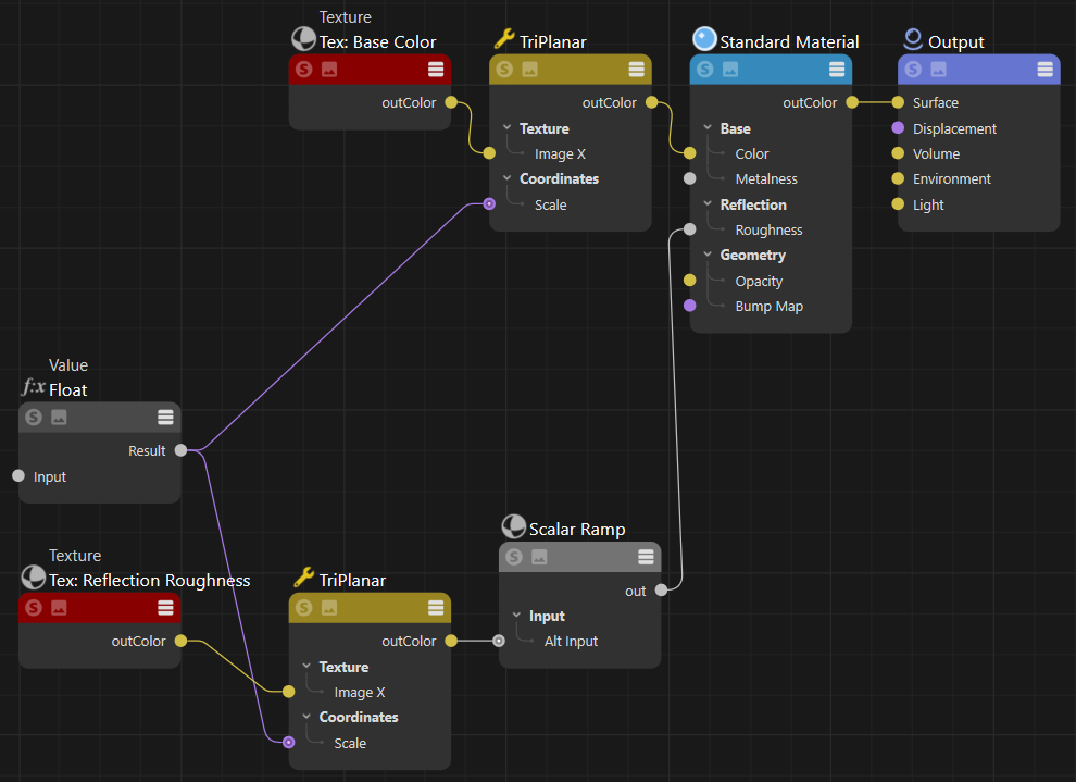
Fig. VII: In this graph, the preview of all nodes has been hidden and the title bar of all Texture nodes has been colored red using a callback function.
The code example shown below uses a callback function to toggle off the preview of nodes and color in “Texture” node title bars. The callback function is called for each node/scope in the graph description. It is used to modify the description before it is applied to the graph. The callback function is passed to maxon.GraphDescription.ApplyDescription() as the argument callback.
import maxon
from maxon import GraphDescription

def MyCallback(scope: dict) -> dict:
    """Realizes a callback function which is called by #ApplyDescription for each node/scope in
    the graph description.

    We use it here to toggle off the preview of nodes and color in "Texture" node title bars.
    """
    scope["Basic/Show Preview"] = False
    if scope.get("$type", None) == "Texture":
        scope["Basic/Color"] = maxon.Color(0.25, 0, 0)
    return scope

# This is the ApplyDescription call where we use our callback function.
graph: maxon.GraphModelRef = GraphDescription.CreateGraph(name="Callback Example")
GraphDescription.ApplyDescription(
    graph, {
        "$type": "Output",
        "Surface": {
            "$type": "Standard Material",
            "Base/Metalness": 1.,
            "Base/Color": {
                "$type": "TriPlanar",
                "Coordinates/Scale": {
                    "$type": "Value",
                    "$id": "texScale",
                    "Input": .02},
                "Texture/Image X": {
                    "$type": "Texture",
                    "Basic/Name": "Tex: Base Color",
                    "Image/Filename/Path": maxon.Url("asset:///file_dcd3db0487f2def6")}
            },
            "Reflection/Roughness": {
                "$type": "Scalar Ramp",
                "Input/Alt Input": {
                    "$type": "TriPlanar",
                    "Coordinates/Scale": "#texScale",
                    "Texture/Image X": {
                        "$type": "Texture",
                        "Basic/Name": "Tex: Reflection Roughness",
                        "Image/Filename/Path": maxon.Url("asset:///file_2e316c303b15a330")}
                }
            }
        }
    # We pass our callback function to ApplyDescription.
    }, callback=MyCallback)
Graph Queries
Graph queries select one or multiple existing parts in a graph to reuse or modify them. The node references introduced in the section Connections and Values are an implicit form of graph queries. When we have the following section in a graph description,
...
"Reflection/Roughness": {
    "$type": "Texture",
    ...
    # Assigning the value "#texTransform" to
    # this port is an implicit graph query.
    "Scale": "#texTransform"
}, ...
then the reference of the Scale port to a node with the identifier #texTransform is an implicit graph query. The graph query is resolved when the graph description is applied to a graph. The query will match a node in the graph that has the identifier #texTransform and connect the Scale port to it. But what we see here is only a shorthand form of a graph query for the special case of connecting a port to a node.
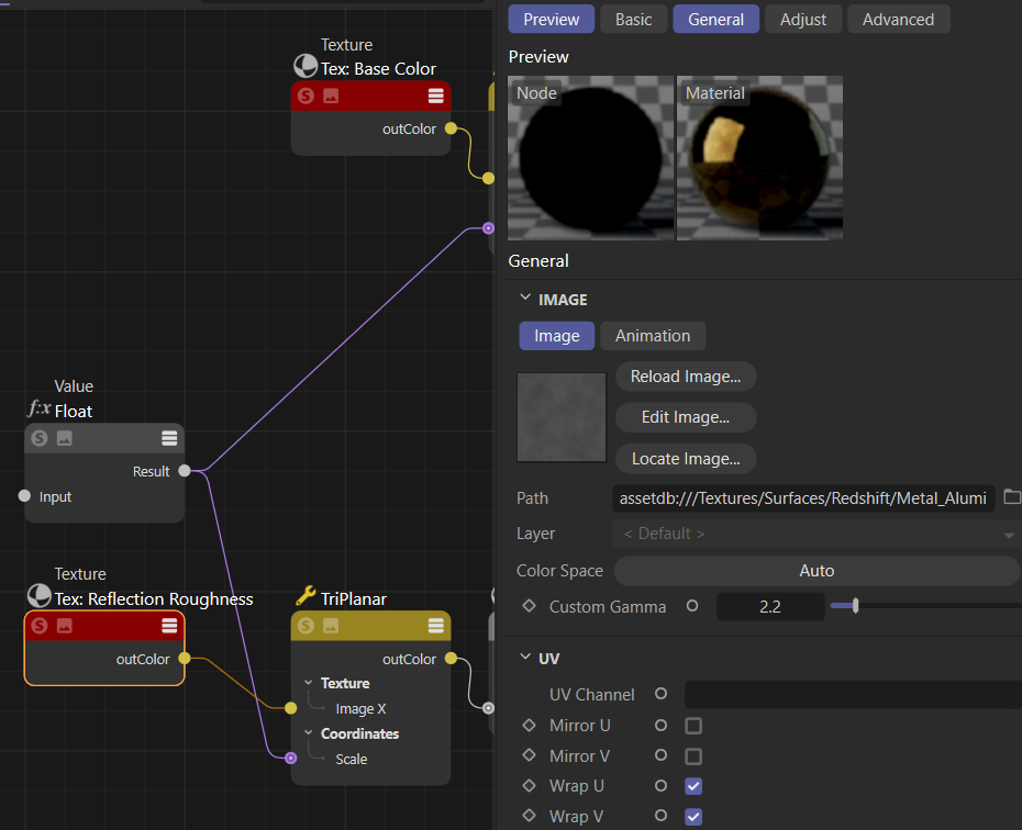
Fig. VIII: The code example shown at the end of this section uses a graph query to all select texture nodes in a material that use the file_2e316c303b15a330 asset. When the example is applied to the output of the Callback example, it will only set the gamma value of the reflection roughness texture because only it matches the query.
Internally, the value of the Scale port will be expanded into a query scope as shown below. We could also write each identifier reference to a node like this, it would have the same outcome as the shorthand form.
...
"Reflection/Roughness": {
    "$type": "Texture",
    ...
    # A new scope is opened to describe a node to connect this Scale port to.
    "Scale": {
        # But instead of setting the type of a new node with the "$type" field, a "$query" field
        # is used to search for a node with certain properties. The scope containing the query
        # will then act as if it was the node matched by the query.
        "$query": {
            # The query will match a node with the ID "texTransform".
            "$id": "texTransform"
        }
    }
}, ...
A graph query is indicated by a scope which does not have the otherwise mandatory $type field and instead a $query field. Assigned to that $query field is then a scope which describes the to be searched node(s). Graph queries can be run both for nodes existing in a graph before a graph description has been applied and nodes that have been created by the currently executed graph description.
Note
Queries currently do not support nested queries where a query scope contains nested scope to define nodes a queried node is connected to. Queried can be at the moment only literal values of a node. The query flag QUERY_FLAGS.SELECT_THIS is intended for nested queries and unused at the moment.
Graph query scopes can have a field called $qmode which is used to specify how the query should be resolved. By default a query will be run as QUERY_FLAGS.NONE which means that the query must match exactly one node in the graph or an error will be raised. When a query is run in the mode QUERY_FLAGS.MATCH_FIRST, the first match will be picked if there is any. If the mode is QUERY_FLAGS.MATCH_ALL, all matching nodes will be picked.
The query mode MATCH_ALL is mostly useful when we want to modify multiple nodes at once. The example shown below uses a MATCH_ALL query to change the gamma value of all texture nodes in a material that use the asset file_2e316c303b15a330. When the example is applied to to output of the Callback example, it will only set the gamma value of the reflection roughness texture because only it matches the defined query.
import c4d
import maxon
from maxon import GraphDescription

doc: c4d.documents.BaseDocument  # The currently active document.

# For each material in the document which has a Redshift material node space.
for material in doc.GetMaterials():
    nodeMaterial: c4d.NodeMaterial = material.GetNodeMaterialReference()
    if not nodeMaterial.HasSpace(maxon.NodeSpaceIdentifiers.RedshiftMaterial):
        continue

    # We use here CrateGraph to get the existing Redshift material graph from #material.
    graph: maxon.NodesGraphModelRef = GraphDescription.CreateGraph(
        material, maxon.NodeSpaceIdentifiers.RedshiftMaterial)

    # We query the graph for all nodes which are of type "Texture" and have the asset file
    # "file_2e316c303b15a330" set as their image file ...
    GraphDescription.ApplyDescription(
        graph, {
            "$query": {
                # Here we define that this query scope is meant to match everything ...
                "$qmode": GraphDescription.QUERY_FLAGS.MATCH_ALL,
                # ... that has the properties defined here ...
                "$type": "Texture",
                "Image/Filename/Path": maxon.Url("asset:///file_2e316c303b15a330")
            },
            # ... so that we can set the gamma value of all matching nodes to 2.2.
            "Image/Custom Gamma": 2.2
        }
    )
Partial Descriptions
Unlike introduced in earlier sections of this manual, a graph description is actually not a Python dictionary but a list of Python dictionaries. A dictionary in that list of dictionaries is called a partial description. When a user only passes a partial description to ApplyDescription, it will be internally wrapped by a list.
But we can also pass the list of partial descriptions ourself. Each dictionary - a partial description - is then applied additively to the graph in the order they appear in the list. Other than showcased by most examples in this manual, a partial description also does not have to define a valid graph, nor does their sum have to. A graph description consisting out of multiple partial descriptions could define a graph with no or multiple end nodes, resulting in both cases in a non-functional graph; but it would be a valid graph description. Partial graph descriptions can be useful for:
Structuring a graph description in a more readable manner. Imagine having a subgraph whose output is used in multiple places in a graph. We can realize such setup as shown here before by defining the subgraph the first time we need it in the main graph and then use its identifier in the remaining places. With partial descriptions we can first define the subgraph in its own partial description and then always just reference it in the main graph description.
Modifying existing graphs. When we want to modify an existing graph, we often want to make multiple modifications at once. Partial descriptions allow us to run multiple queries on a graph in a row and modify it with each query.
Adding multiple sub-graphs not connected to a singular end-node in the graph. Imagine for example preloading a material with a handful of texture setups to be manually wired into a more complex setup by an artist.
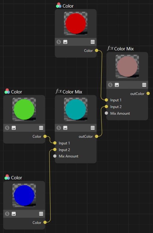
Fig. VIV: The output of the simple partial description example shown below. Each Color node has been added by a separate partial description, and only the fourth partial description created the two Mix Color nodes and wired up all nodes.
import c4d
import maxon
from maxon import GraphDescription

GraphDescription.ApplyDescription(
    # A graph description actually consists of a list partial descriptions applied to a graph.
    GraphDescription.CreateGraph(name="Partial Descriptions"), [
    # First we have three partial descriptions that add the Color nodes for red, green and blue to the graph.
    {
        "$type": "Color",
        "$id": "red",
        "Inputs/Color": maxon.ColorA(1, 0, 0, 1)
    },
    {
        "$type": "Color",
        "$id": "green",
        "Inputs/Color": maxon.ColorA(0, 1, 0, 1)
    },
    {
        "$type": "Color",
        "$id": "blue",
        "Inputs/Color": maxon.ColorA(0, 0, 1, 1)
    },
    # If we would end our description here, we would just have added three Color nodes to the graph. But we
    # add a fourth partial description to add the two Color Mix nodes and wires up all five nodes.
    {
        "$type": "Color Mix",
        "Mix Amount": 0.5,
        "Input 1": "#red",
        "Input 2": {
            "$type": "Color Mix",
            "Mix Amount": 0.5,
            "Input 1": "#green",
            "Input 2": "#blue",
        },
    }]
)
Resource Editor
An important aspect of using the Nodes API is the Resource Editor of Cinema 4D. This also applies to some degree to graph descriptions, as constants such as the value of data type or the value dropdown are not always known to the user. The Resource Editor can be used to discover these constants and their identifiers. The Resource Editor can be opened by pressing SHIFT + C and typing its name in the Commander.
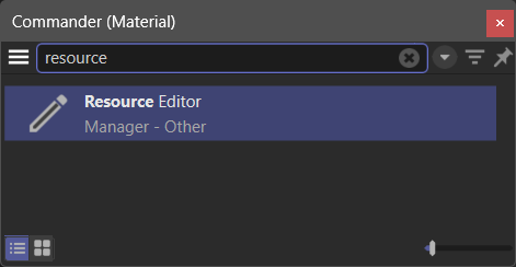
Fig. X: To open the Resource Editor, press SHIFT + C and type its name.
The Resource Editor is GUI for the databases - the resources - that make up data types and interface elements of parts of Cinema 4D which have been realized using the maxon API. You will not find anything classic API related in the Resource Editor, especially not the resources of a classic API NodeData plugin. The Editor can be split into seven sections as shown below:
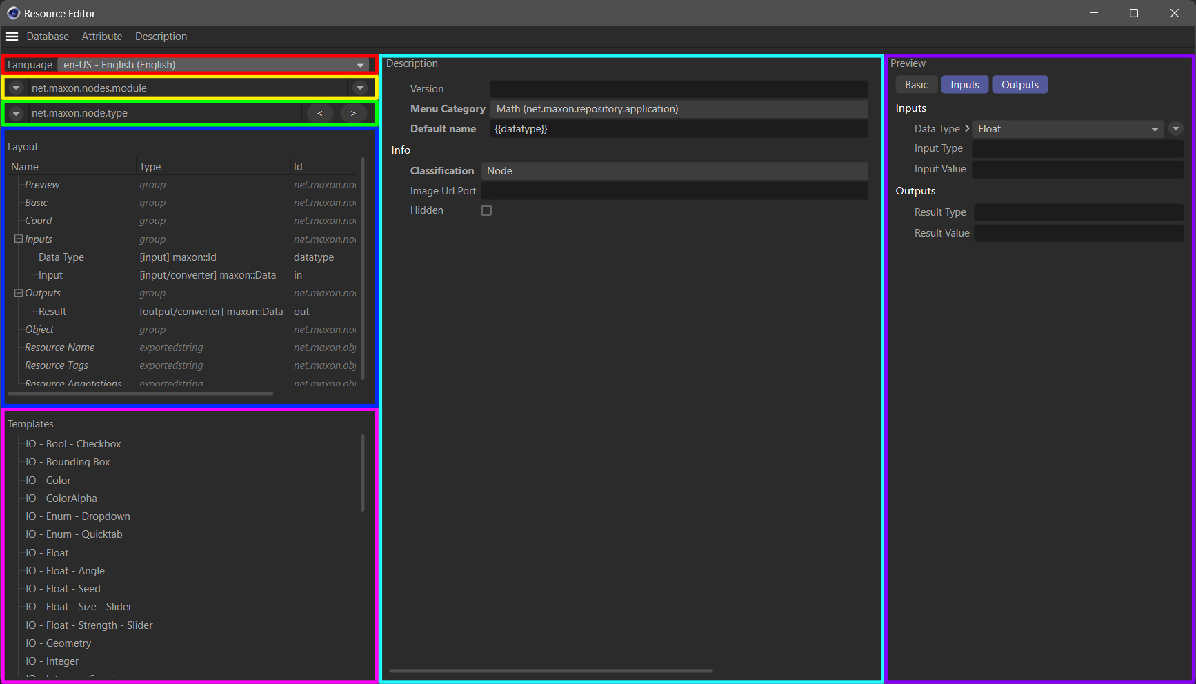
Fig. XI: The main sections of the Resource Editor.
Language (left side, red): Selects the browsed interface language. This will impact the values of localized strings in resources and should be set to “en-US” when working with graph descriptions as they currently only support English interface labels.
Database (left side, yellow): Selects a database. All elements that are not root elements in the attached menu are not databases but entities in that database, i.e., we can select a database and an entity in it in one operation. A database is usually context bound, e.g., Redshift material nodes have their own database.
Entities (left side, green): Selects an entity in the selected database. An entity can be the description of a node type or a data type - and some other cases. The Resource Editor calls the elements of a database descriptions which is just terminological noise. Think of them as the resources/entities of the selected database.
Structure (left side, blue): Displays the structure of the selected entity. Here we can find attribute groups, attributes, ports, fields, and more elements of the selected entity.
Templates (left side, pinks): Provides a set of ready made templates for an entity. This field is irrelevant for graph descriptions.
Editor (middle, teal): This is the editor for the currently selected entity. Here we can see its string, GUI, and data settings and also edit them when we have write access to the database.
Preview (right side, purple): Shows a preview of the selected entity. This is not relevant for graph descriptions.
To find the identifiers of a port or attribute value, we must find the node which holds the port or attribute. Let us assume we want to set the Input Map Type port of a Redshift Bump Map node. We cannot use interface labels but must use the identifier instead.
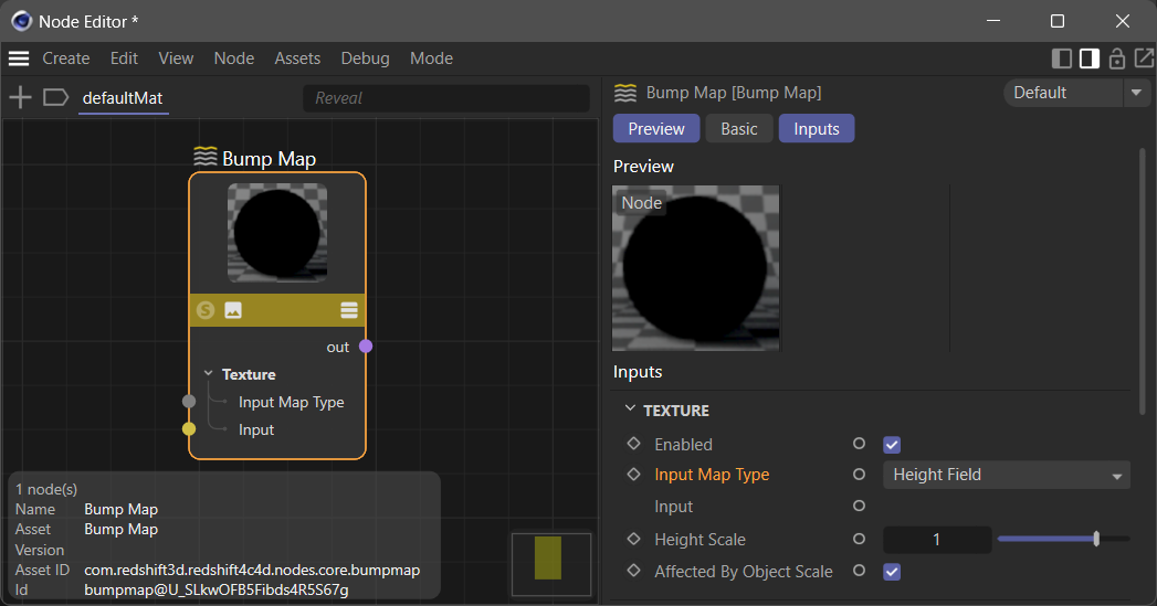
Fig. XII: We want to discover the raw values a Redshift Bump Map node Input Map Type port can take.
Ee search for the Bump Map node in the Resource Editor by typing the word bump in the opened database context menu to narrow its content down. It is here helpful to know the API identifier of the node as shown in the Node Editor because entities are stored under their API identifier in Resource Editor databases. We then select the Input Map Type input port in the Structure section of the selected Bump Map entity. The Editor section will then show us the raw values the enum of the port can take in its Enum List field. The values are 0, 1, 2 in this case. By expanding the Enum List field, we can also explore the label-value pairs of the enum in more detail.
Fig. XIII: Using the Resource Editor to find an enum value.
Another common task is to find data types, this can be done analogously by for example searching for file to find the port-bundle datatype Filename used for example in a Redshift Texture node. Sometimes we must also find out the API identifier of a data type, for example when we must set the data type of a Value Node. And while we could do that with the Resource Editor, it is often easier to use the special private _dt field of a maxon.Data instance for that. We can either use the console to print the identifier or make use of the field in a graph description.

Fig. XIV: We use the console and a dummy instance to find out the identifier of all maxon data types.
Alternatively, we can also use the _dt field in a graph description:
import maxon
from maxon import GraphDescription

# Unless we set the data type of a Value node to a specific type, it will only work for real
# numbers.
GraphDescription.ApplyDescription(
    GraphDescription.CreateGraph(name="Data Types"), {
        "$type": "Value",
        # We use the _dt field to set the data type of the Value node to a color with an alpha.
        "Data Type": str(maxon.ColorA()._dt),
        "Input": maxon.ColorA(1, 0, 0, 1)
    }
)
Examples
Not yet documented.
